Service mode setting parameters
For further information on functions and settings in the CDV commissioning software, see the RV 2 installation and commissioning instructions.
 Factory settings for the following parameter setting values in bold.
Parameter 1: Unit type on RLS (Fan1, Fan2)
No function for RV 2.
Parameter 2: Number of unit pairs, unit types PP 45 and PPB 30 O
No function for RV 2.
Parameter 3: Deactivating ventilation level 0
|
| 1 = Ventilation level 0 activated. 2 = Ventilation level 0 deactivated. The ventilation units cannot be switched off on this control. The units run at least at level 1. |
Parameter 4: LT power units, RLS 45 K room air controls (on the RS 485 bus)
|
| Configuration for parallel operation of several LTs / RLS. 0 = no further LTs/RLS |
Parameters for linking this room air control with other room air controls (RLS) or power units (LTs).
Example: Two further RLS (RLS #2 and #3) are connected to RLS #1.
Setting value at RLS #1 = 2 / Setting value at RLS #2 = 4 / Setting value at RLS #3 = 5.
Parameter 5: 230 VAC input
|
| 1 = Sleep mode 4 = Supply air mode without overrun, for volumetric flow compensation for exhaust air fans (ECA/ER (60m³/h)) 4 to 6: Activate volumetric flow compensation using RV 2 units additionally via commissioning software. 230 V input with switching contact, additional function can be used with button or switch, see Connection and wiring diagram, "S1". Recommendations: Use a button for the sleep mode and intermittent ventilation functions (reacts to falling edge). |
Parameter 6: Sensors
|
| 0 = No sensors |
Parameters for using the connected internal and external sensors. The internal sensor PP 45 HYI and the external sensors PP 45 HY, PP 45 CO2 and PP 45VOCare available.
Parameter 7: EnOcean
|
| For activating the EnOcean extension module PP 45 EO. 0 = EnOcean module not present |
Parameter 8: EnOcean Teach mode
No function for RV 2.
Parameter 9: Number of PPB 30 K units
No function for RV 2.
Parameter 10: ModBus settings
ATTENTION: The ModBus interface must be deactivated for RV 2 units, otherwise RV 2 units cannot be controlled.
Parameter 11: ModBus address
No function for RV 2.
Parameter 12: Plug & Play
|
| Automatic search run for pairwise assignment of the supply air and exhaust air units. 0 = Manual settings with CDV commissioning software 1 = Plug & Play: Start automatic search For further information → following chapter. |
Exit setting mode
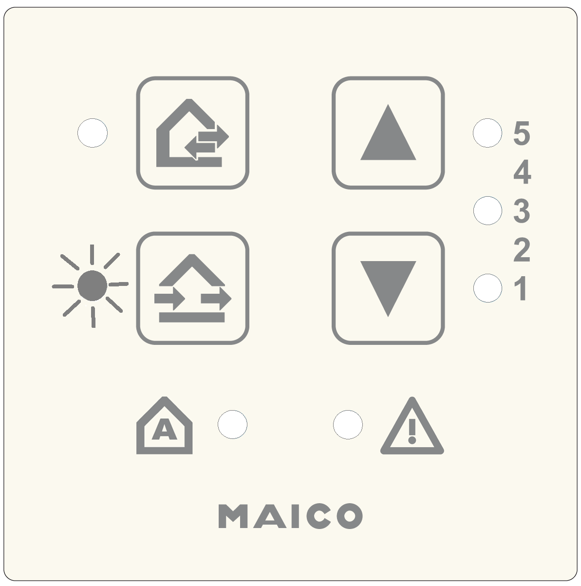
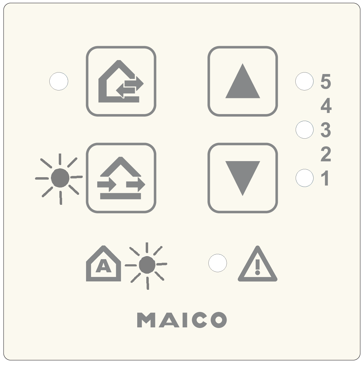
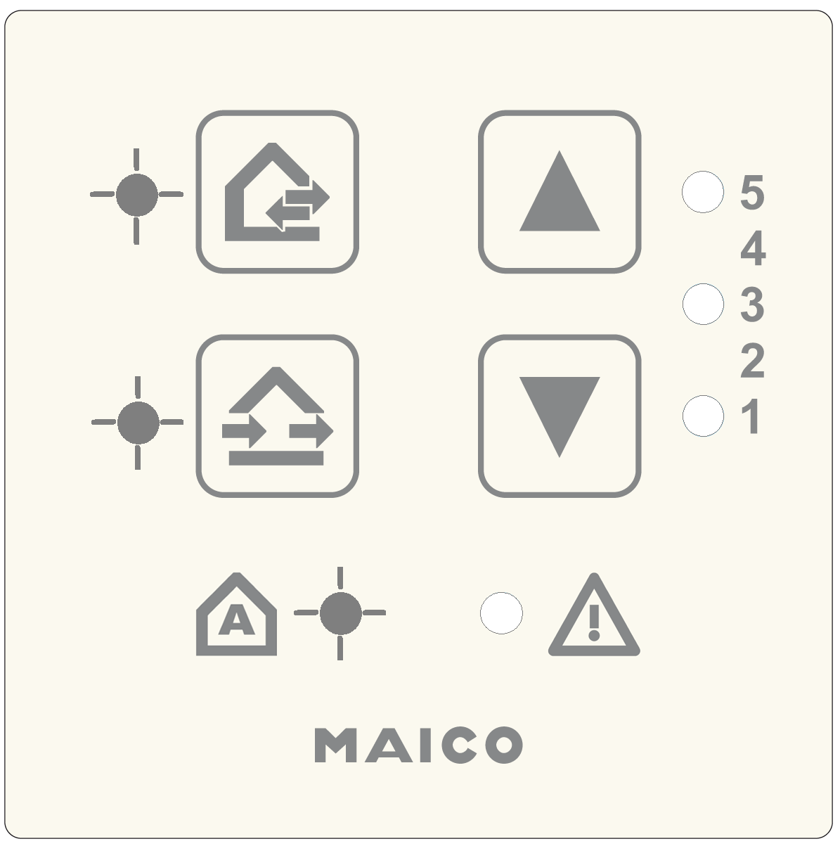
Press the  and
and  buttons together for 5 seconds. The ventilation unit switches to the specified ventilation level.