Installation of the fan unit
→ ER/Centro installation and operating instructions
→ Fig. 14 of the main instructions:
The VZC-2/GVZC-2 circuit board is fitted in position [18] in the fan unit.
The VZC-2/GVZC-2 fan unit can be combined with all ER-UP housing units (ER-UPB, ER-UPD and ER-UP/G).
EC circuit board
For circuit boards → Figs. 14 and 15 of the main instructions.
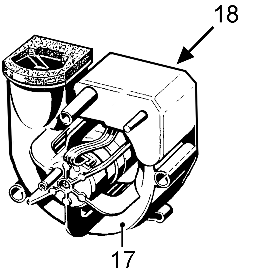
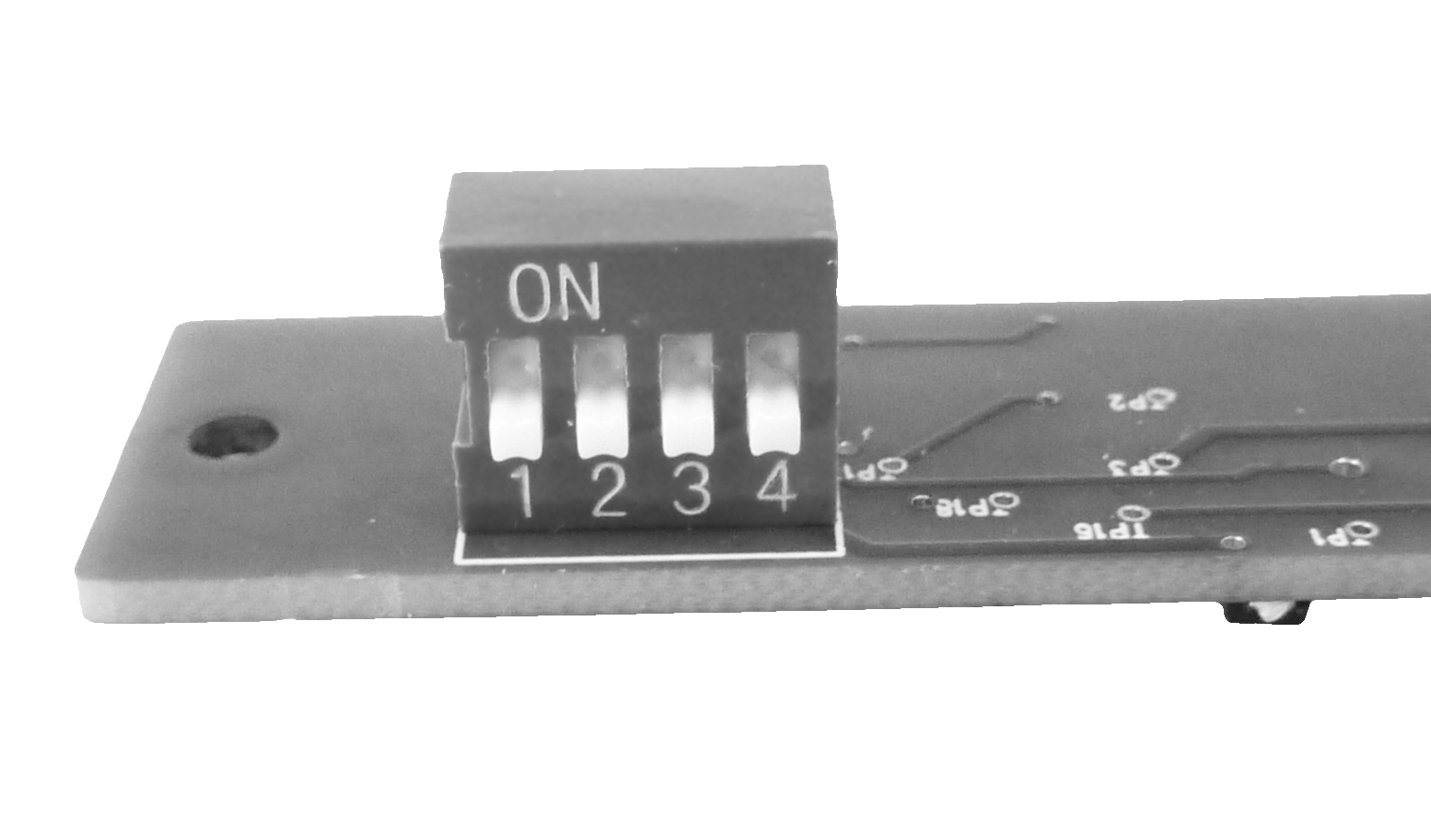
Circuit board [18] and DIP switches [18.2]
Factory settings
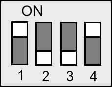
- Start delay = 50 seconds
- Run-on time = 15 minutes.
Pin 1 | Pin 2 | T start delay [s] |
| Pin 3 | Pin 4 | T run-on [min] |
|---|---|---|---|---|---|---|
OFF | OFF | 0 |
| OFF | OFF | 3 |
ON | OFF | 50 |
| ON | OFF | 6 |
OFF | ON | 100 |
| OFF | ON | 15 |
ON | ON | 150 |
| ON | ON | 24 |