RLS 45 K room air control (master control)
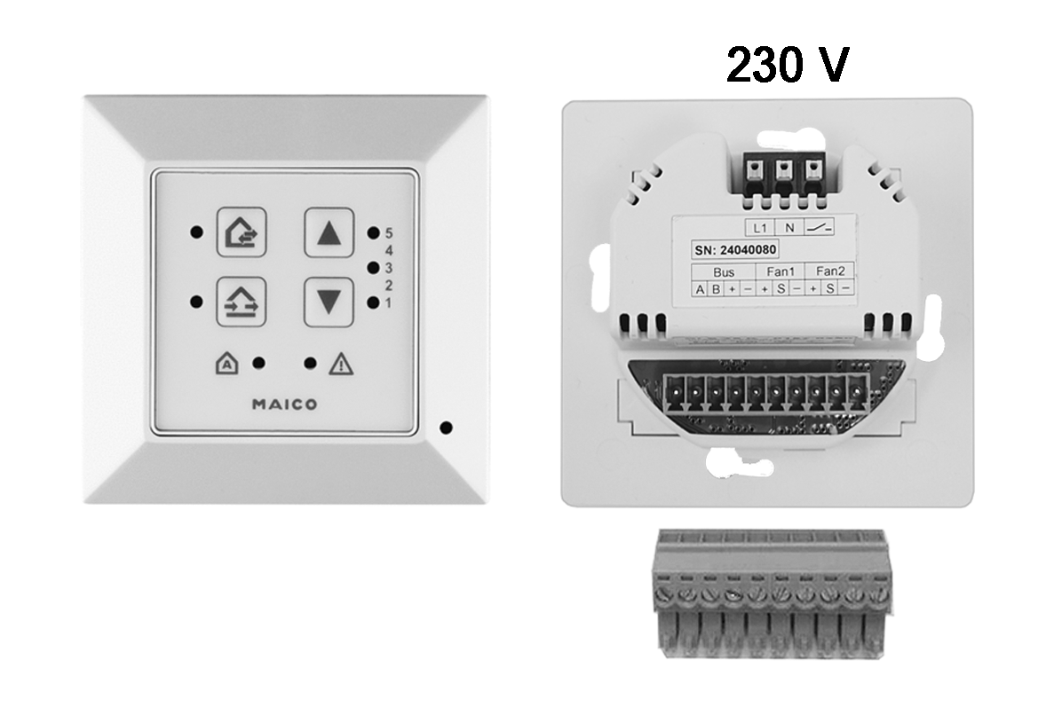
The control centre for the CPP 60 ventilation system is an RLS 45 K room air control unit (230 VAC) used as a master control unit.
Possible system extensions on the RS 485 bus
- up to three additional RLS 45 K control units (slaves)
- up to three PP 45 LT power units
- up to 8 CPP 60 ventilation units (12 VDC) per RLS 45 K master control
- 1 PP 45 HYI internal humidity sensor
- external sensors PP 45 HY, PP 45 CO2 or PP 45 VOC
- 1 EnOcean wireless module PP 45 EO.
Installation instructions
- The additional components must be activated in the service menu or with the commissioning software.
- Mixed systems consisting of PP 45 and PPB 30 units are permitted.
Observe the maximum permissible number of ventilation units, system components and connection lines. Avoid imbalances caused by cable runs of different lengths and different power consumption.
 DANGER due to electric shock. Serious injuries/death.
- If there is no or insufficient separation between the 12 V extra-low voltage and 230 V.
Ensure a safe distance between 230 V and 12 V (SELV).
Ensure a minimum distance of 8 mm.
Ensure a phase balance between all components connected to the ventilation system. - When installing the RLS 45 K room air control, the CPP 60 ventilation unit or the PP 45 LT power unit within protection zone 0, 1 or 2 and ingress of moisture.
No IP protection available (IP 00).
The installation of CPP 60, RLS 45 K or PP 45 LT is only permitted outside protection zones 0, 1, 2. - DANGER due to short circuit or fire. Serious injuries/death.
- In the event of moisture penetrating the control unit.
Ensure a correct, tight cable feed. - In case of overload due to incorrect connection or connection of too many units to an RLS 45 K.
Connect the ventilation units according to the connection diagram.
Comply with the permissible number of ventilation units per room air control/power unit.
Mounting the control unit
- Switch off the mains fuse and secure it against being switched on again.
- Carefully remove the outer frame of the RLS 45 K.
- Cut the power cable and connection cable to length.
- Wire the CPP 60 ventilation units with the RS 485 connector plug (bus terminals), see plug sticker and Connection and wiring diagrams.
- Insert the connector plug into the RLS 45 K.
- Insert the RLS 45 K into the flush-mounted box and screw it to the box using 4 screws.
- Attach the outer frame. When using a PP 45 HYI sensor, ensure that the sensor opening is correctly positioned over the HYI and that the frame snaps into place.
- Switch on the mains fuse and start up the ventilation system, see chapter Commissioning, setting parameters.
- Call up the service menu and activate the system components.
 Use the automatic search function (Plug & Play) for an even number of CPP 60 units. The ventilation units are automatically assigned in pairs.