Installation preparations for surface mounting
Installation instructions
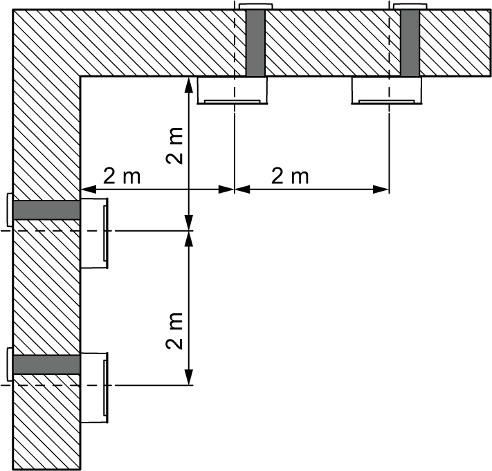
- Observe minimum spacing.
- Ensure sufficient space to work in front of the unit → filter change.
- The customer should provide appropriate fixing material for installation.
- Core hole diameter DN 140.
The condensate is drained via the external cover.
 Recommendation: To prevent dirt from depositing on the façade around the external cover, fit a water-repellent plaster system.
- For wall thickness, see technical data.
- Select installation position so as to avoid contamination and draughts.
- Units/controls are not suitable for outdoor use. Protect ventilation units/controls from moisture and wetness.
- The ventilation units and controls are not suitable for use in protection zones → Danger of electric shock in the event of moisture ingress.
- Use room air control and radio switch only outside protection zones 0, 1 and 2.
- • Use ventilation units only outside protection zones 0, 1 and 2.
- Ventilation units: Install a maximum of eight CPP 60 per master control/system.
- Controls: In addition to the master controller, 3 further controllers (slaves) are permitted on the RS 485 bus.
- Keep a minimum distance of 2 m between 2 ventilation units if they are in heat recovery mode, otherwise ventilation short circuit.
- For required connection cables → Connection and wiring diagrams.
- Grid connection and 230 V input: 3x type NYM-J 5G 1.5 mm²
- Control cables: Type J-YSTY, 0.8 mm, 4-wire (12 VDC, GND, A, B). Max. 25 m from star point, up to star point max. 4 m
- Incorrect measurements if the installation location of the control and external sensors is inappropriate. Avoid disturbing influences and direct sunlight.
- The LED brightness on the RLS 45 K can be set using the commissioning software. The LEDs can also be switched off if they are disturbing (bedrooms).