Preparations for wall installation
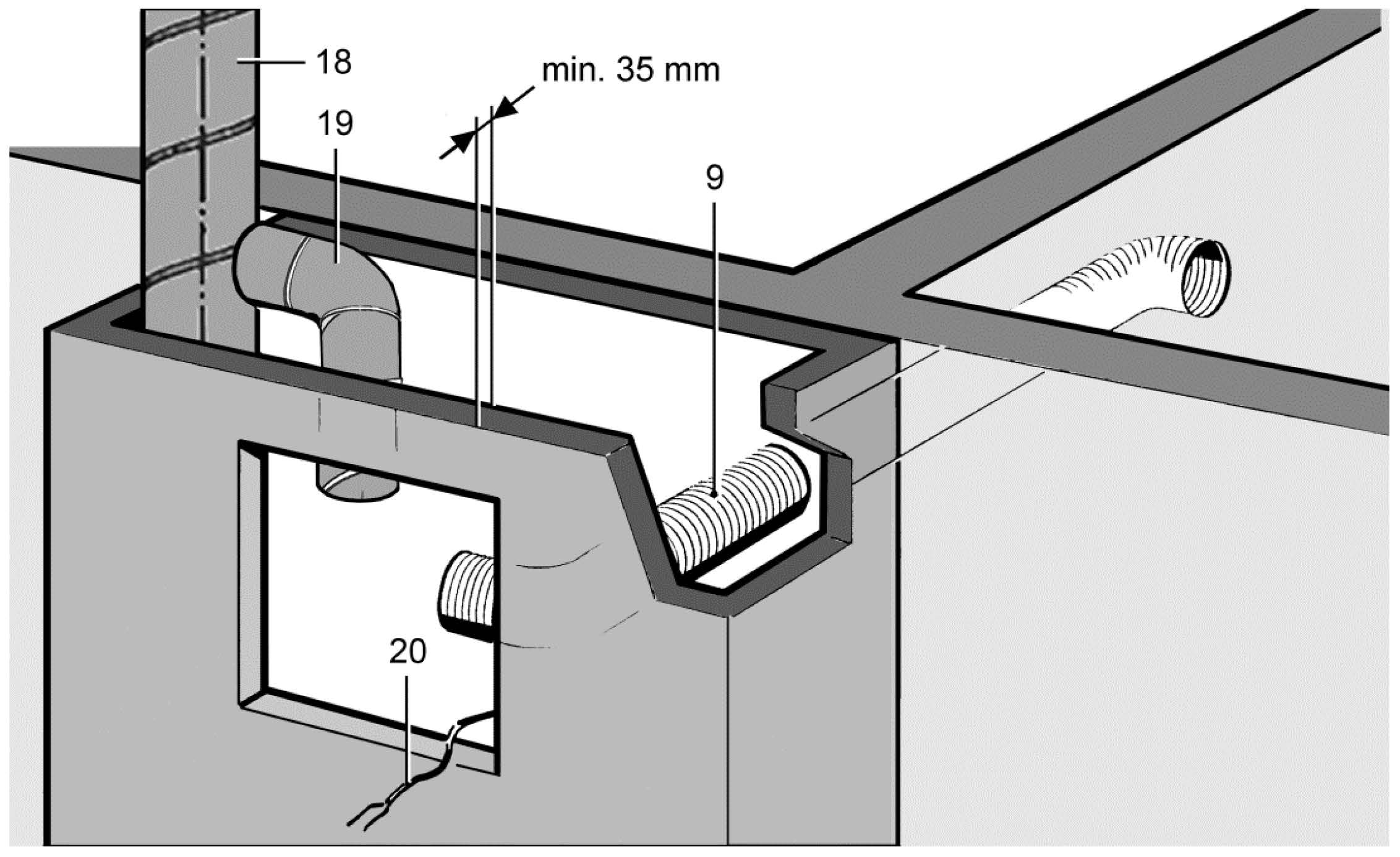
9 | Suction duct for second room connection on ER-UPD EC: Flexible aluminium duct AFR 75/AFR 80 |
18 | Main duct: Steel folded spiral-seams duct |
19 | Connection duct on |
20 | Power cable |
Installation instructions
- Observe approval: Certificates of approval and Requirements in line with approval.
- Always use correct duct material for the housing.
- For fire protection systems, the gap remaining between the connection duct and brickwork/wall boards/wall/ceiling must be fully sealed with non-flammable materials that are resistant to deformation (e.g. concrete, cement mortar, fire protection filler).
 NOTICE Damage to unit, malfunctioning in the event of corrosion damage from mortar.
- Wrap ventilation ducts, connected to the unit, with a suitable adhesive tape to protect against corrosion inside the brickwork, e.g. using cold-shrink tape.
Preparing the shaft
- Produce opening in shaft or alternatively produce a wall facing. Ensure a suitable, flat surface for the housing so that the fan insert can be safely inserted in the housing later on.
- For a second room connection, produce an opening in the wall or shaft for the suction duct. Note permissible housing installation positions.
- Correctly attach main ventilation duct inside the shaft.
- For fire protection systems, use ceiling compound. To do this, encase the ceiling and pour in the material from above.
- Connect connection duct, suitable for the housing, to the main duct and seal for ventilation.
- Cut connection duct to length, note a maximum duct length of 2 m.
- Lay suction duct and seal gap remaining correctly as described in previous installtion instructions.
- Lay power cable in shaft and allow to protrude by around 30 cm above the shaft opening.
- In the ceiling area, fit a spigot made from shaft material F90 around the shaft.
- Lay power cable: Provide unit with electrical connection.