Electrical connection
 Observe the relevant regulations (DIN EN 50110-1 and DIN EN 60204-1 in Germany), especially VDE 0100 with the corresponding parts. Before starting work on the electrical system, switch off the mains fuse and secure it against being switched on again (padlock). Attach a warning sign in a clearly visible place. Observe information on thermal overload protection Thermal overload protection. If prescribed, use motor protection switches or thermal contacts. Do not exceed usage temperatures.
- Remove the terminal compartment cover [2].
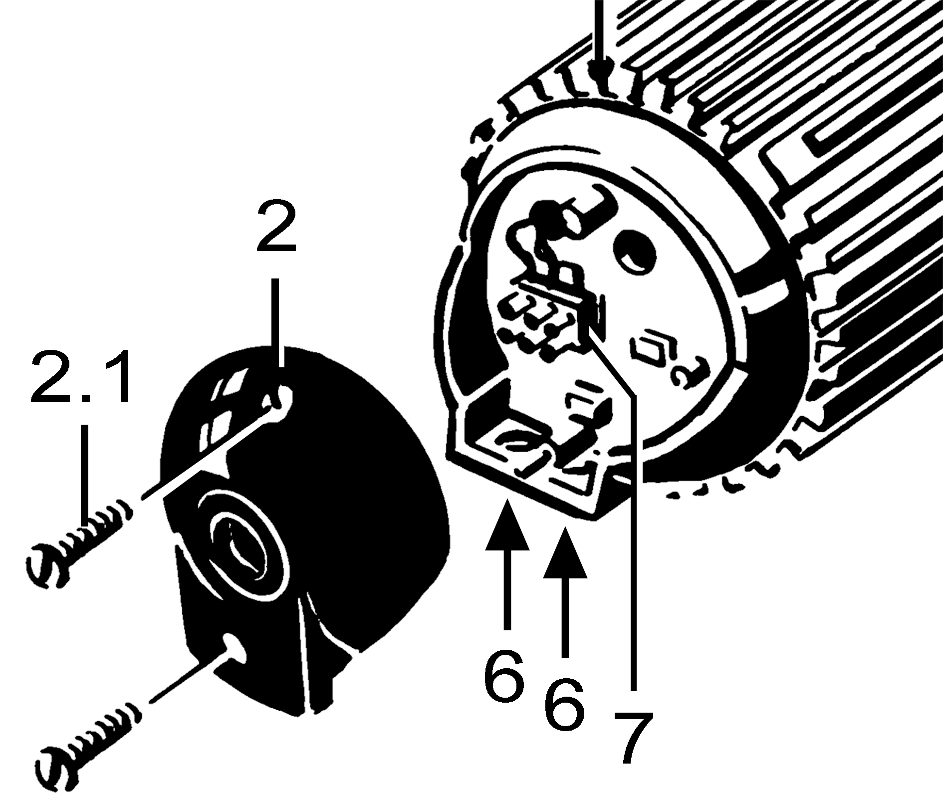
- Pierce the cable grommet [6] and lead the power cable through the grommet into the terminal compartment. Ensure correct cable feed and tight grommet (IP 54/IP 55). If necessary, seal the cable grommet on site.
- Electrically wire the fan to the terminal block according to circuit diagram (Internet) (tightening torque of screws 0.7 Nm). Check PE conductor connection (tightening torque of screw 1.5 Nm).
 CAUTION Risk of injury with EZQ../EZS.. and capacitor not installed or incorrectly installed
The motor can start even if the stationary impeller is touched lightly.
- Only EZQ.. B/EZS B: Electrically wire capacitor [4] to the terminal block (tightening torque of screws 0.7 Nm). Connect the PE conductor to the earth terminal (tightening torque of screw 1.5 Nm).
- Only DZQ../DZS..: Connect external control device to the two TK motor terminals of the terminal block. (Tightening torque of screws 0.7 Nm).
- Connect on/off switch (on-site).
- Connect optional accessories.
- Check that the technical data (rating plate) matches.
- Fit terminal compartment cover [2].
- Tighten both screws to a tightening torque of 1.5 Nm.
- WARNING Risk of electric shock when removing/mounting protective grille
- Check that the protective grille is firmly seated and carry out a PE conductor test.
- Switch the mains fuse on.