FE 100/1 AP and FE 100/1 SG: Installation in windows or thin walls
Observe the applicable regulations for electrical installations, e.g. DIN EN 50110-1 and DIN EN 60204-1, in Germany in particular VDE 0100 with the corresponding parts.
- Before working on the electrical equipment, switch off the mains fuse and secure it against being switched on again. Observe safety instruction supplementary sheet.
- Select the required number of spacing frames depending on the pane thickness.
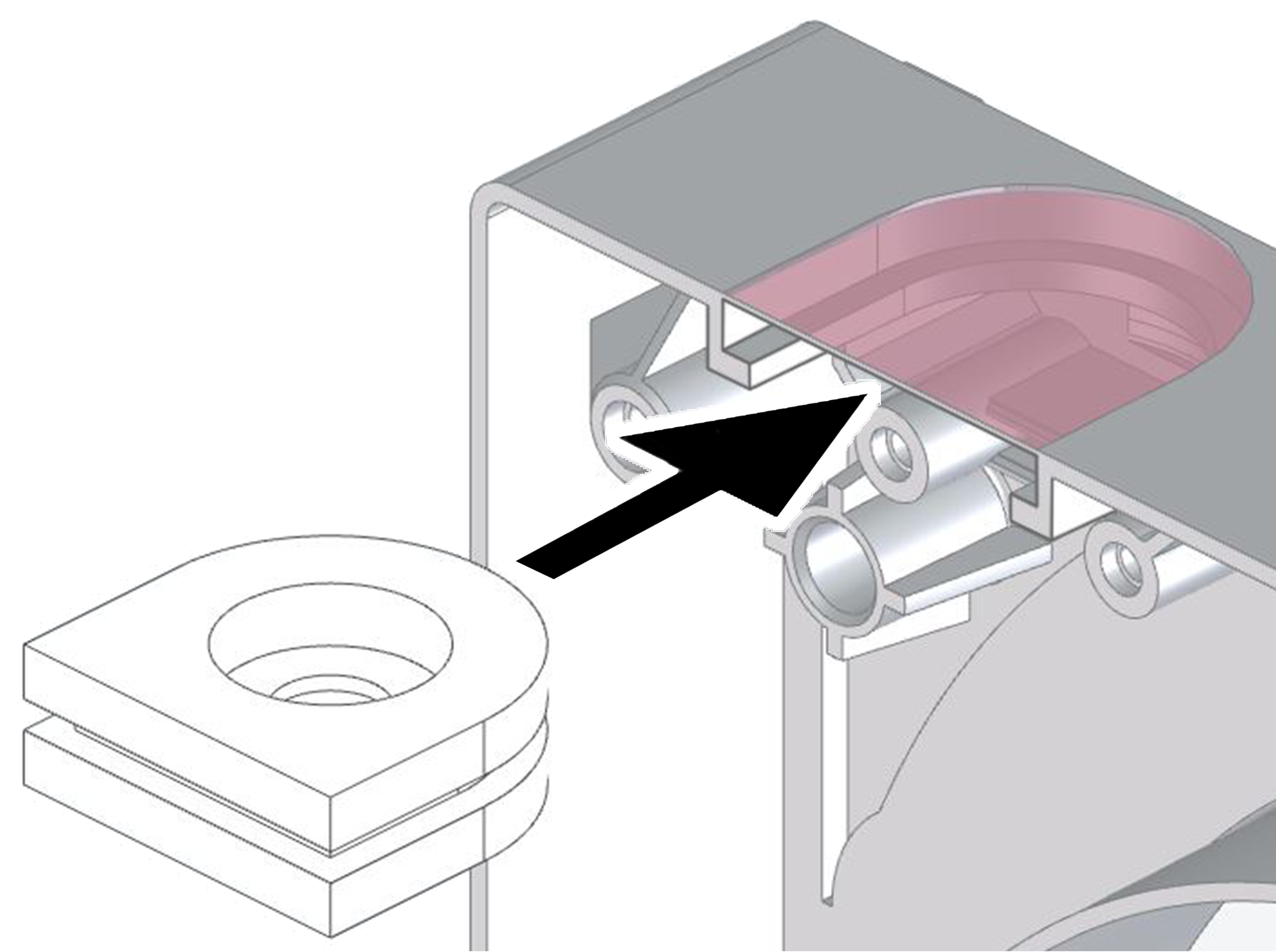
- Cut out the opening provided in the housing on a spacing frame and insert the cable grommet.
- Pierce the cable grommet with a screwdriver and feed the power cable through the grommet. Ensure that the cable grommet is correctly fitted and tight.
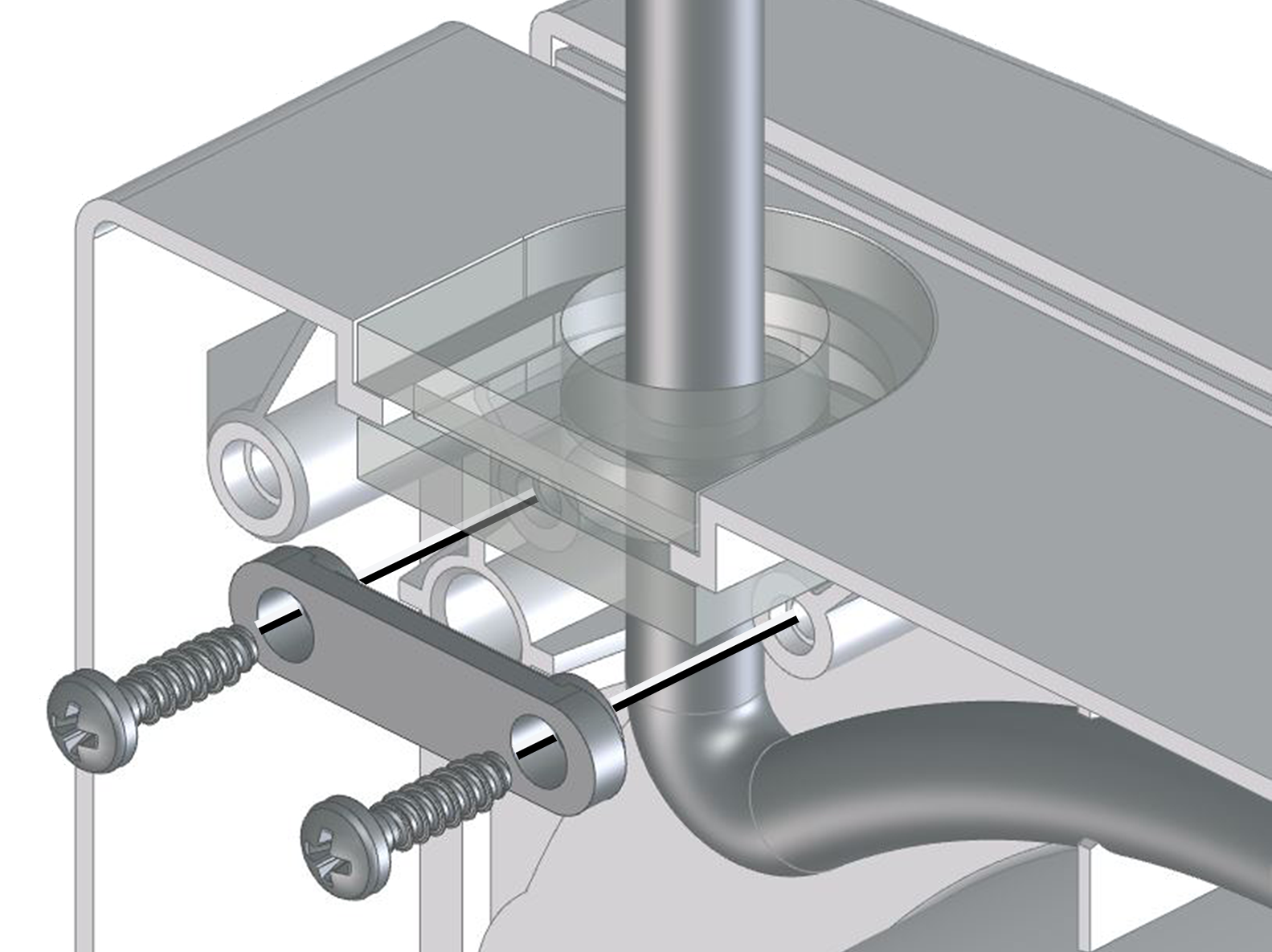
- Fasten the power cable with the tension relief and route it to the right in the spacing frame.
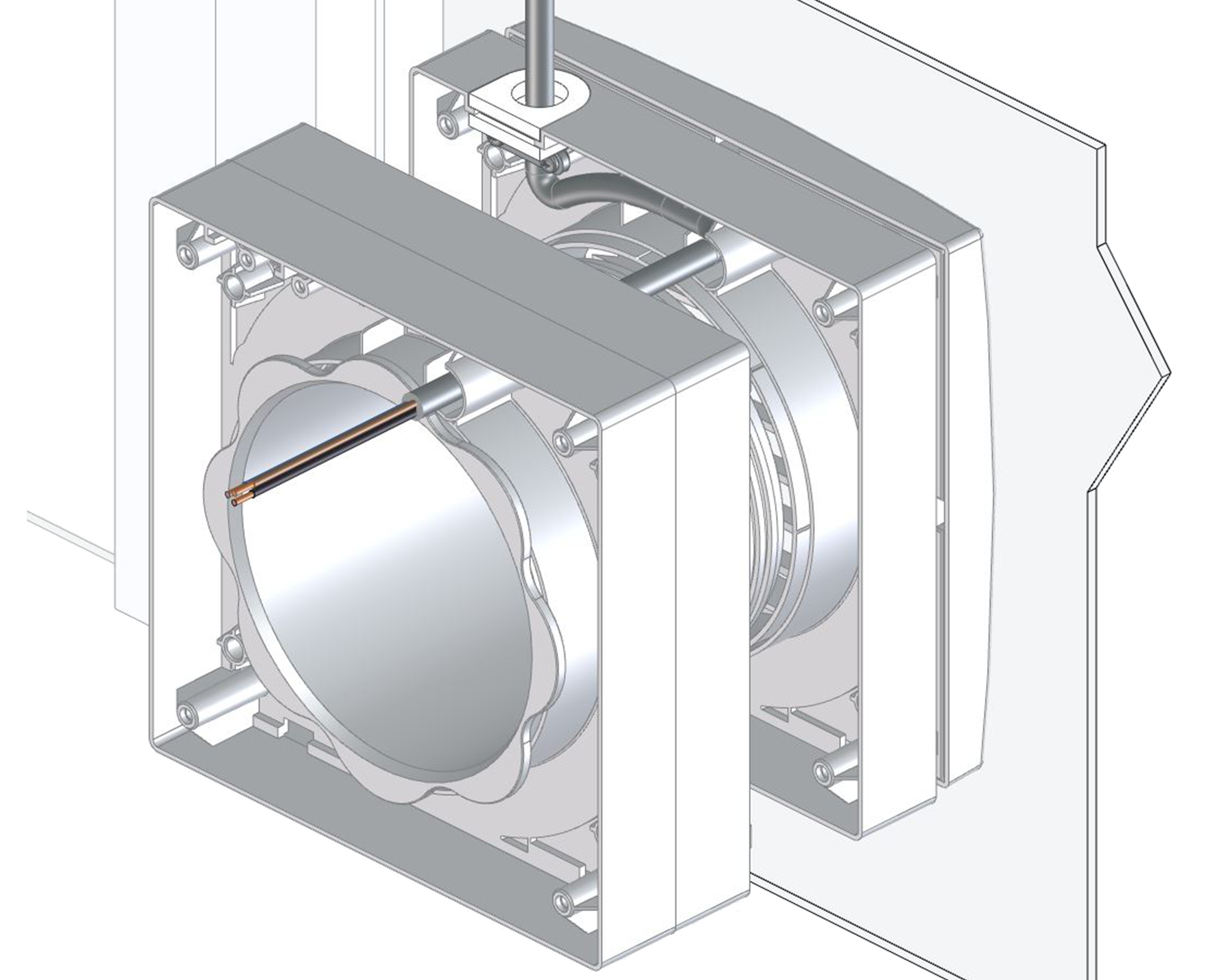
- Push the power cable through the 10.5 mm hole in the other spacing frame.
- Press the spacing frames into each other until they audibly click into place and form a block.
- Place the sealing ring on the external shutters/external grille adapter, guide the adapter through the window pane cut-out and press it against the outer side of the window.
- Place the other sealing ring on the spacing frame with the cable grommet and press the entire spacing frame block against the inner side of the window. Align all parts and screw together with the threaded connector. The two sealing rings must lie flat against the pane.
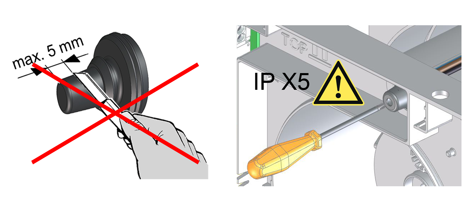
- Pierce the cable grommet of the ECA 100 ipro with a screwdriver. Only make a thin hole in the grommet.
 DANGER due to short circuit/fire if moisture penetrates into the terminal compartment. In the event of incorrect cable installation, the electronics cover cannot be used flat/sealed. Observe the permissible cable length in the terminal compartment. The grommet must be fitted firmly and tightly in the housing, even with the power cable.
NOTICE IP protection is only guaranteed if the cable grommet of the ECA 100 ipro is properly pierced. Do not cut the cable grommet as described in the ECA 100 ipro installation instructions.
- Feed the power cable through the cable grommet of the ECA 100 ipro into the fan terminal compartment. The cable grommet must tightly enclose the cable sheathing of the power cable to ensure IP X5.
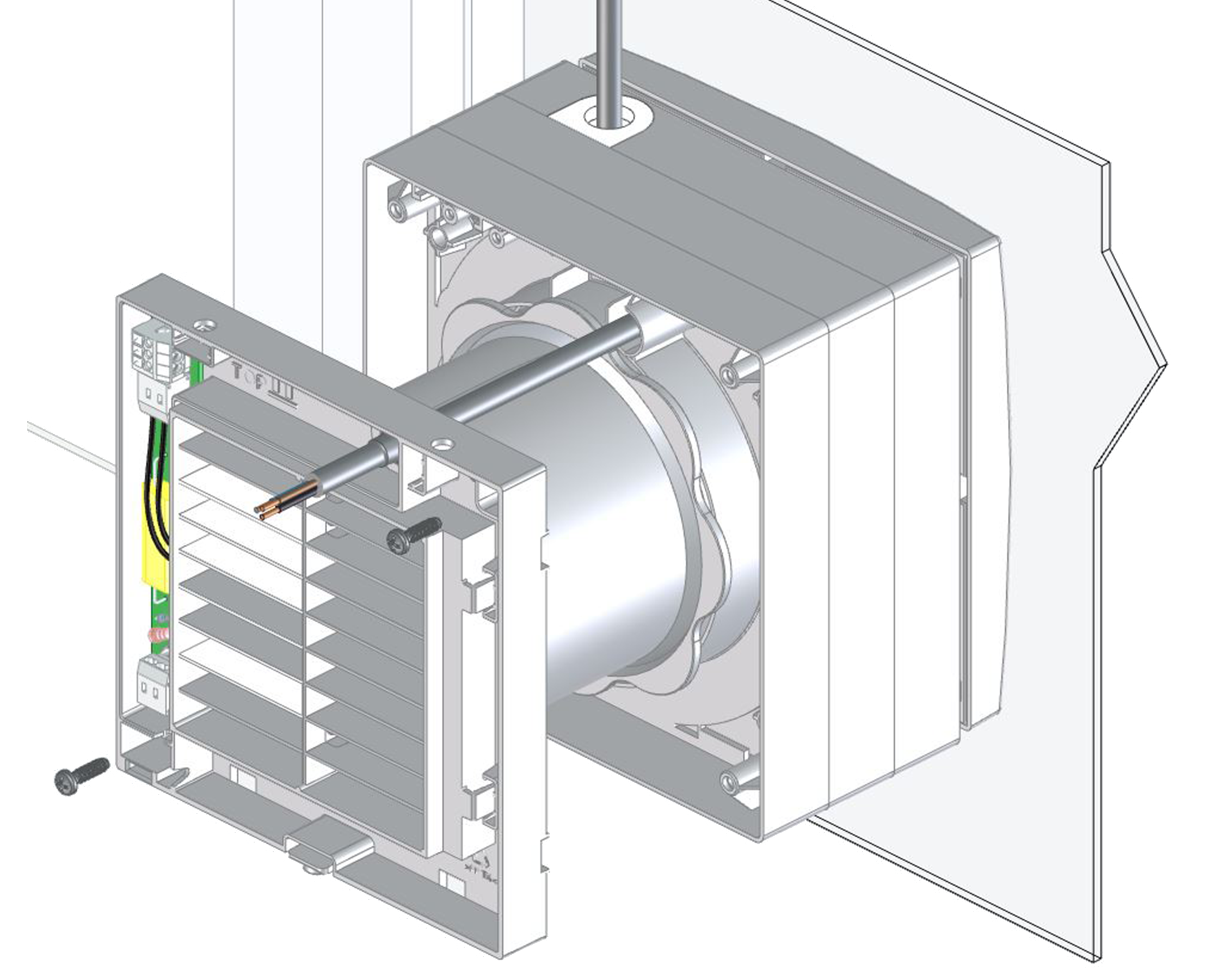
- Screw the fan to the spacing frame with 2 screws.
- Fit fly screen and cover on the outer side.
- Install and electrically wire the ECA 100 ipro in accordance with the relevant installation instructions.