Connection diagram for RLS 45 O / PP 45 O
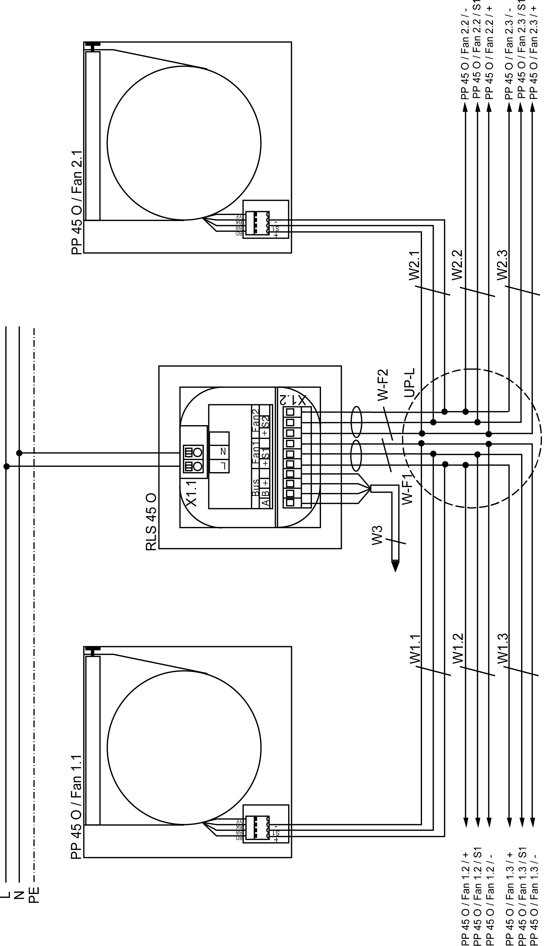
RLS 45 O | PushPull 45 Object room air control |
PP 45 O | PushPull 45 Object ventilation unit |
Fan 1.1 | Ventilation unit 1, unit pair 1 |
Fan 2.1 | Ventilation unit 2, unit pair 1 |
Fan 1.2 | Ventilation unit 1, unit pair 2 |
Fan 2.2 | Ventilation unit 2, unit pair 2 |
Fan 1.3 | Ventilation unit 1, unit pair 3 |
Fan 2.3 | Ventilation unit 2, unit pair 3 |
UP-L | Flush-mounted distributor for connection of ventilation units. Connection of all ventilation units in a star configuration to the distributor |
W-F1: Fan 1 | Control line for Fan 1/Fan 2: |
W1.X | Ventilation unit control cable. |
W3 | Bus connection cable (RS-485). Recommended control cable J-Y (ST) Y 2x2x0.8 mm. |