Cleaning PPB 30 ventilation unit
- Have ventilation unit cleaned by a specialist installer every 2 years.
- Clean internal grille, fans and electronics cover with a dry cloth.
Clean all ventilation units as follows:
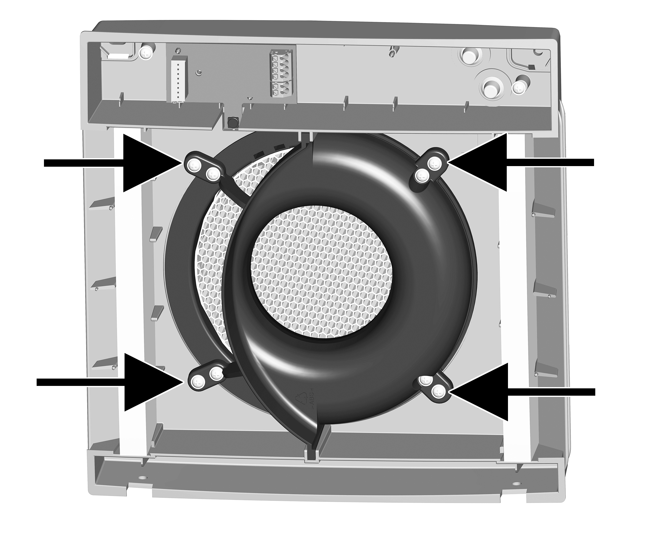
- Remove the 4 screws (→ arrows) of the slide-in module.
- Pull off both connector plugs on circuit board.
 Risk of injury/damage to unit from falling slide-in module.
Sometimes the slide-in module (3.6 kg) is hard to pull out. Ensure that you are standing securely and cannot lose your balance and that there is no one under the unit. When installing and removing the slide-in module, support it from below with a hand.

20 | Slide-in module |
33 | Internal cover of fluid distributor |
34 | Centring ring |
- Pull the complete slide-in module out of the wall sleeve. Also pull the pipe extension all the way out.
- Use a vacuum cleaner to clean the slide-in module while still assembled.
- If very dirty, disassemble the slide-in module.
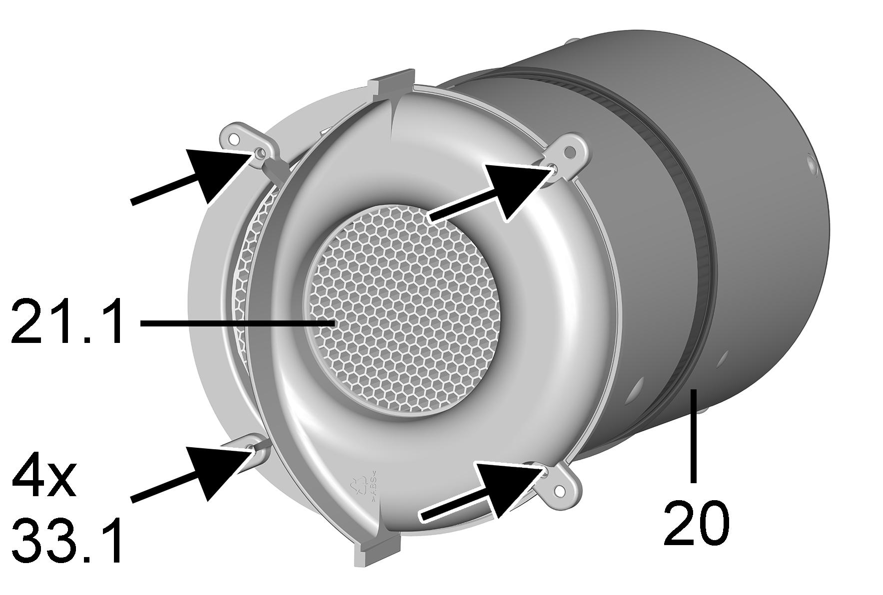
20 | Slide-in module |
21.1 | Ceramic heat exchanger |
33.1 | Screws |
To do this, remove the 4 screws of the fluid distributor internal cover, take out profile seal and remove ceramic heat exchanger.
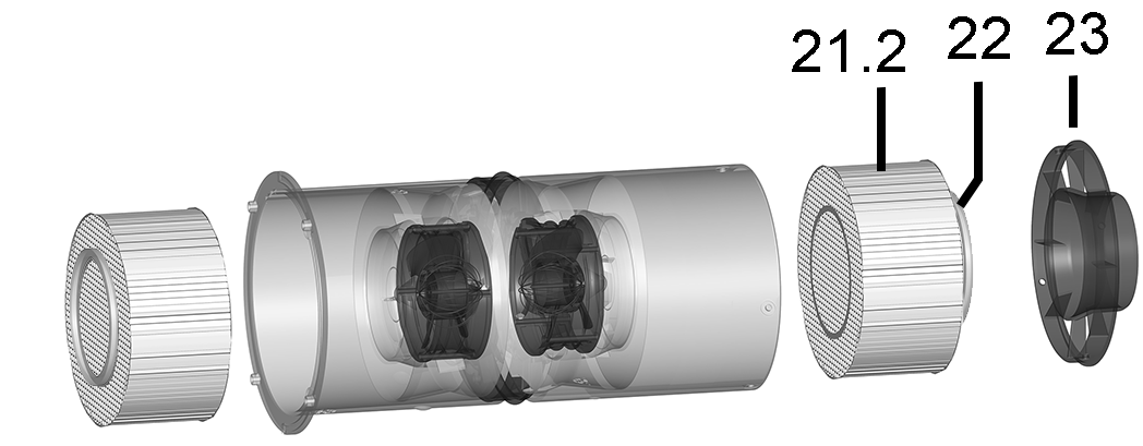
21.2 | Ceramic heat exchanger |
22 | Profile seal |
23 | Fluid distributor slide-in module |
Then remove fluid distributor slide-in module (4 plastic rivets →Cleaning PP 45 ventilation unit) and pull fluid distributor out of the slide-in module. Take out profile seal and remove ceramic heat exchanger. Rinse out both heat exchangers with water and leave to dry.
- Assemble the slide-in module in reverse order. Only insert a dry heat exchanger.
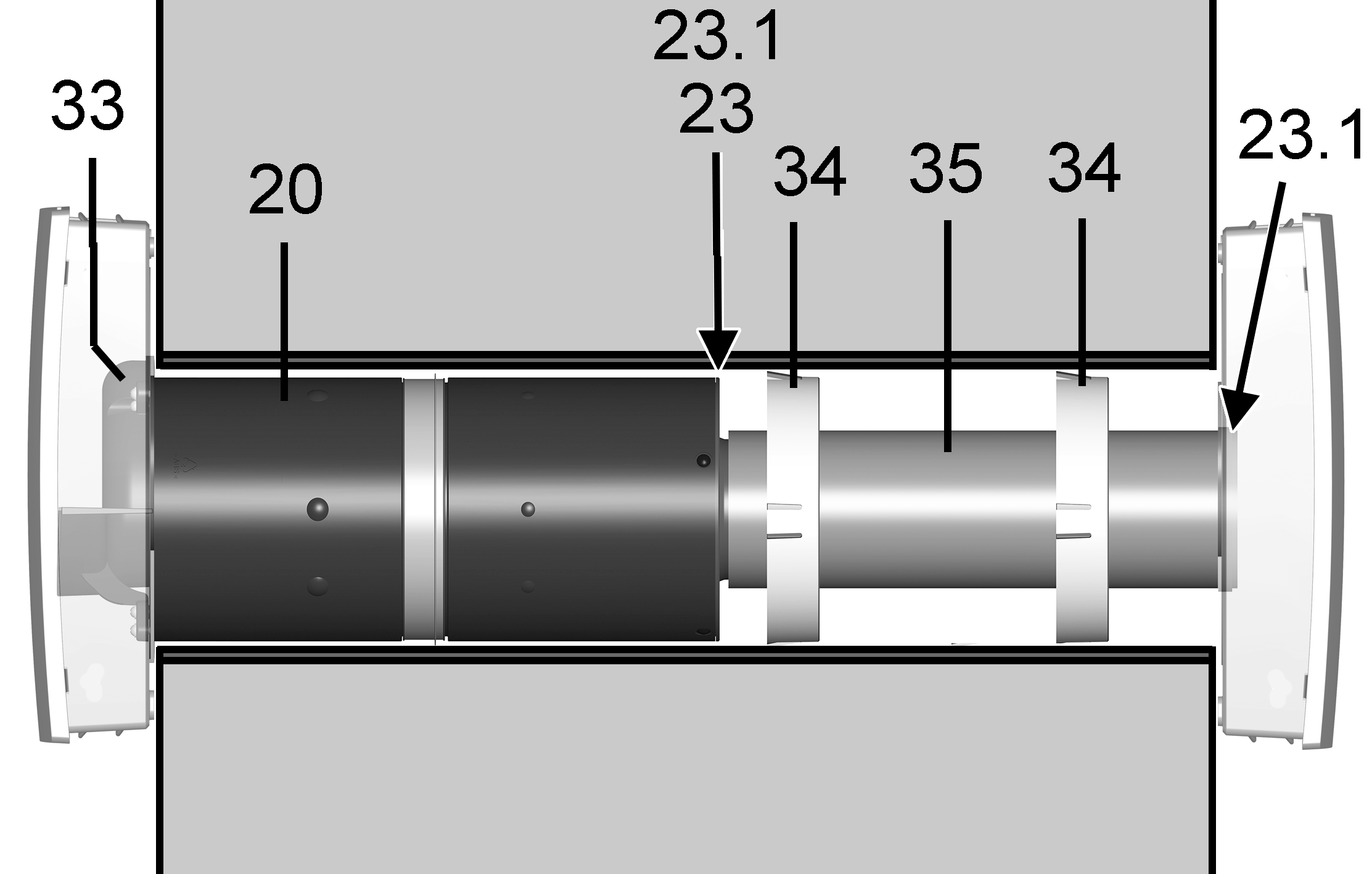
20 | Slide-in module |
23 | Fluid distributor slide-in module |
23.1 | Sealing strip |
33 | Internal cover of fluid distributor |
34 | Centring ring |
35 | Pipe extension |
Damage to brickwork caused by condensation if sealing strip on fluid distributor slide-in module and at end of extension is incorrectly glued/is not sealed and the entire unit is not slid in up to the stop.
Before installing, ensure that the sealing bands are flush at the face end (face against face), are not one on top of the other and are not overlapping.

23 | Fluid distributor slide-in module |
23.1 | Sealing strip |
35 | Pipe extension |
- Ensure that the sealing strip is flush all the way round at end of fluid distributor and at end of extension. This must not have any holes or tears to prevent incorrect air from infiltrating the wall sleeve.
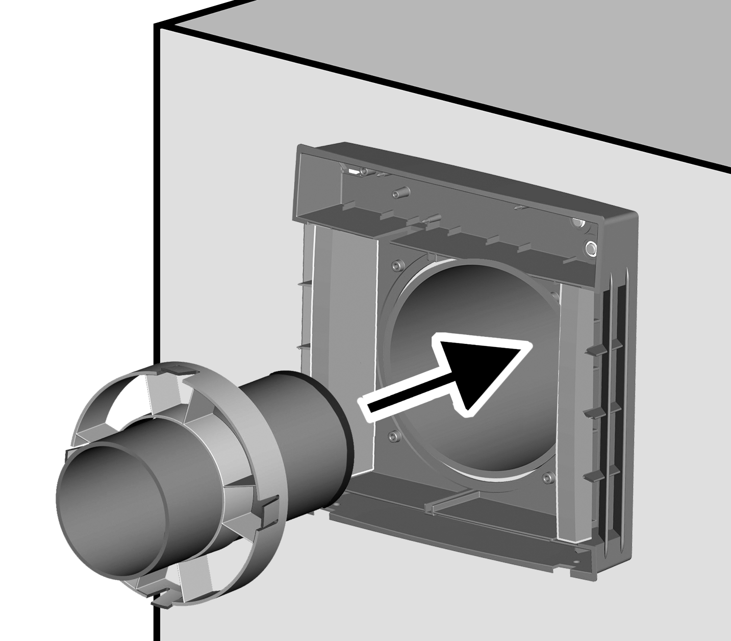
- Slide extension into wall sleeve with centring ring(s) up to stop of external cover. Ensure that the side with the gasket is facing the external cover and that the centring ring is positioned as far inside as possible. If using a long extension (> 200 mm), use two centring rings
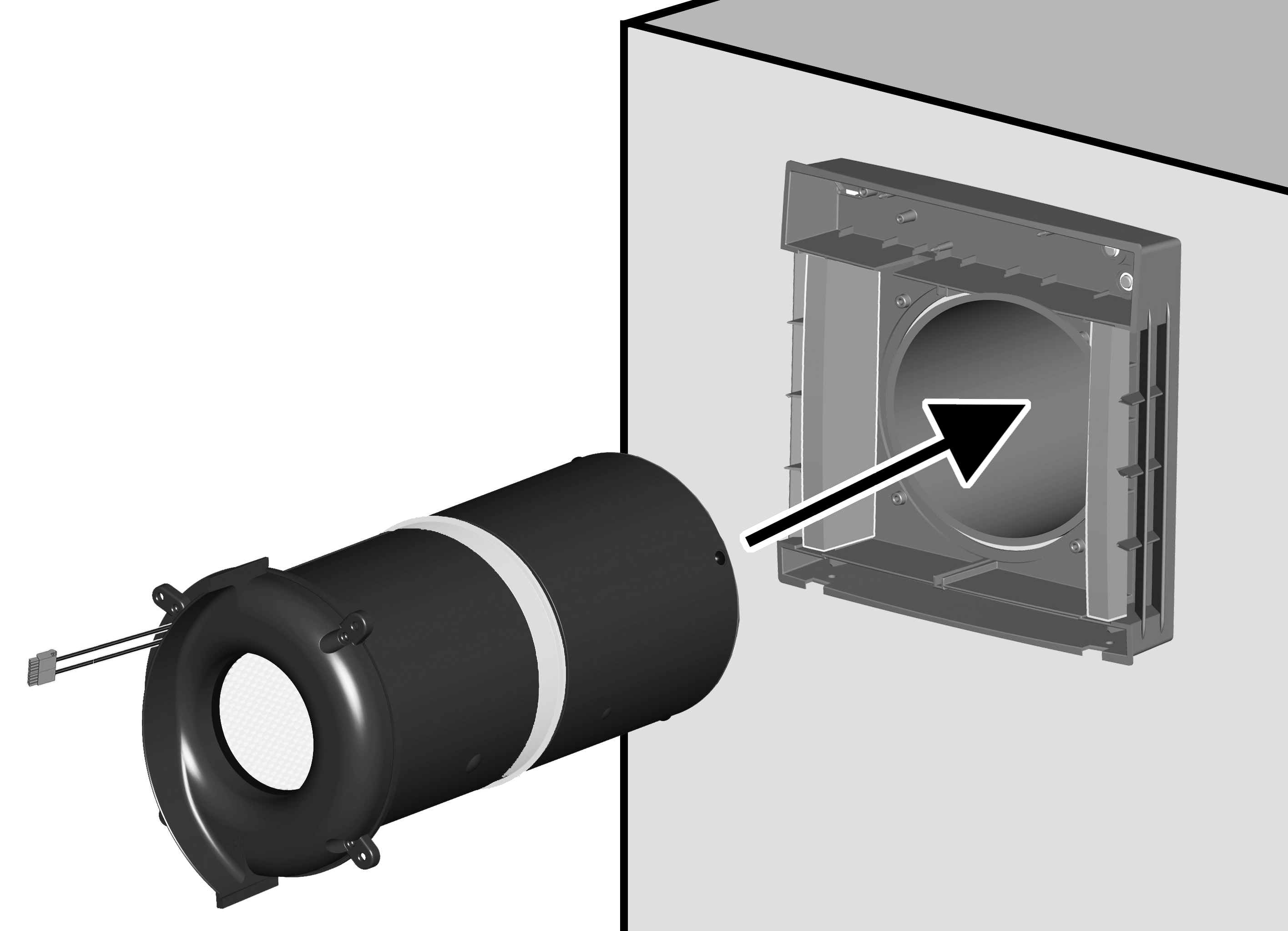
- Slide slide-in module into wall sleeve up to stop of extension (motor connection cables must be at the top). Gasket on fluid distributor must make full contact with the extension.
- Screw down slide-in module with internal cover (4 screws).
- Plug in plug (8-pin) of both fan connection cables directly on circuit board and guide cables into the grooves and/or channels provided for this purpose. With PPB 30 K, ensure that the humidity sensor is exposed.
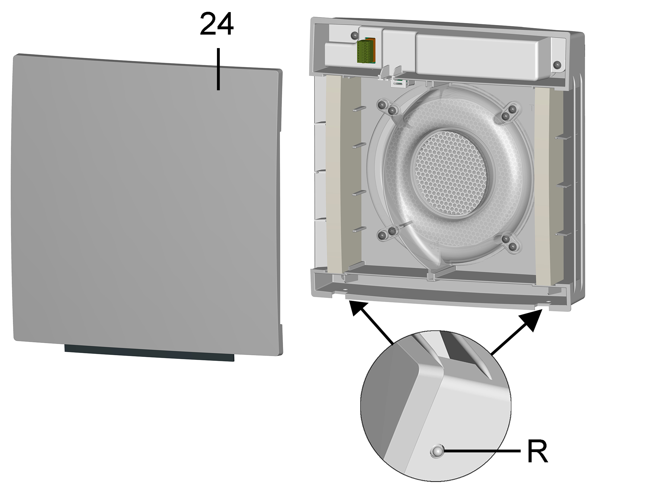
24 | Front cover of internal housing |
R | Latches |
- Attach front cover internal housing at top in two internal housing studs and swivel down until the front cover engages with the two latches.
- Remove warning sign from fuse box and switch on mains fuse. The ventilation units start up in ventilation level 2.
- Run function test.