Electrical connection
Observe the applicable regulations for electrical installations, e.g. DIN EN 50110-1 and DIN EN 60204-1, in Germany in particular VDE 0100 with the corresponding parts.
 DANGER due to electric shock
Observe the safety rules of electrical engineering. Before taking off covers and before installing the electrics, shut down all supply circuits, switch off mains fuse, check that no voltage is present, secure against being accidentally switched back on and position a visible warning sign.
DANGER Risk of short circuit/fire if moisture penetrates the electronics compartment. Short circuits and fire can lead to serious injuries with fatal consequences.
Ensure correct, tight cable feed through the cable glands and long-hole diaphragm grommet.
CAUTION Risk of injury due to sharp edges on sheet metal/break-outs in the housing or in the electronics compartment.
Wear protective gloves. Carefully guide connecting cables into unit. Do not damage cables.
 If the connecting cables are too short, the electronic slide-in module cannot be fully pulled out and fitted on the housing. Ensure connection cables of a sufficient length inside the ventilation unit.
A fixed wiring for the mains connection is mandatory. The power cable is already wired inside the unit and led out of the unit.
Take electronic unit with main board out of ventilation unit and attach as described below.
- Switch off the mains fuse and secure it against being switched on again.
- Remove front panel and internal cover → Mounting the ventilation unit on the wall.
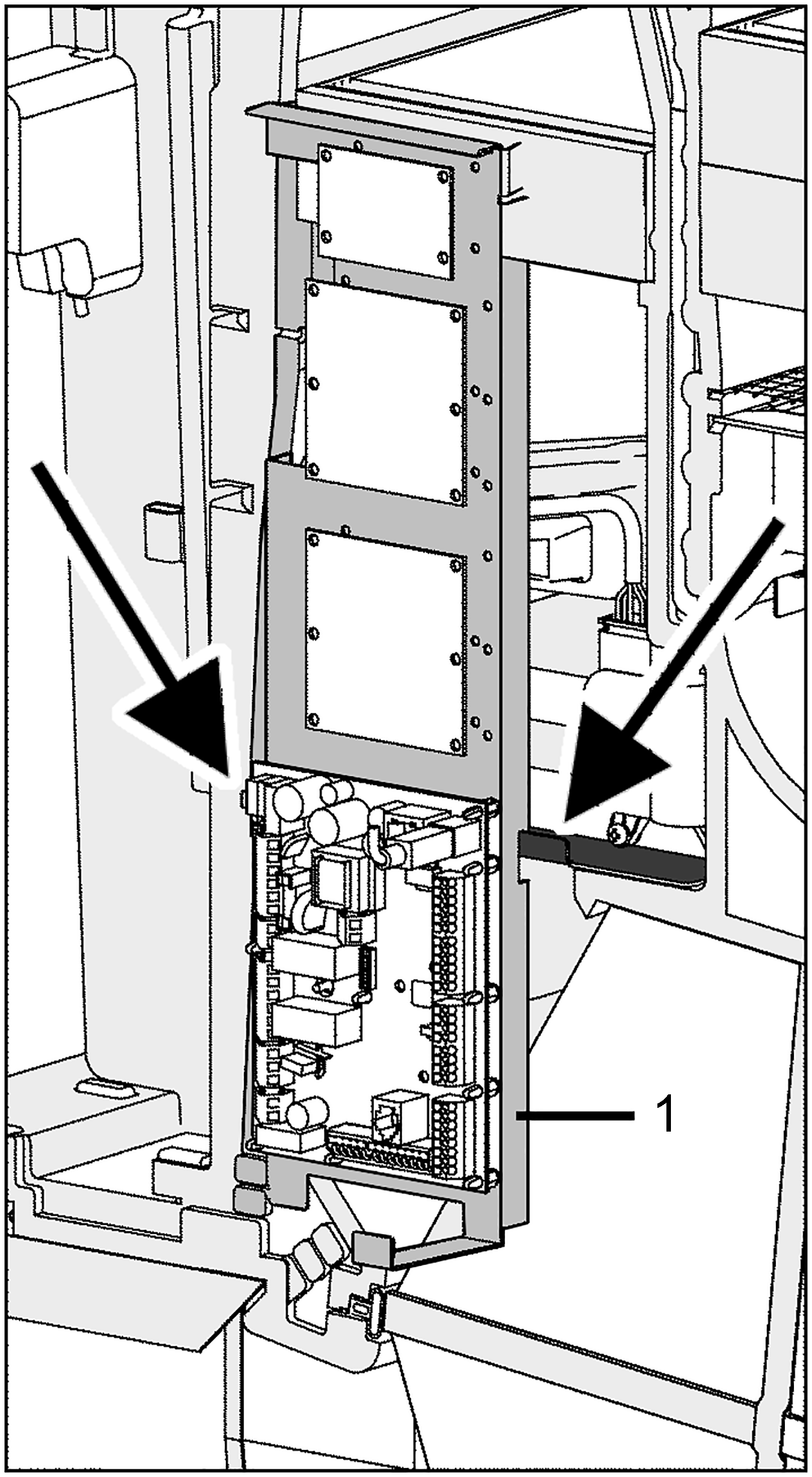
Fig. Left-hand version of the ventilation unit (the right-hand version is mirror-inverted)
1 | Electronics slide-in module |
Arrow | Fitting studs |
- Lift the electronics slide-in module (with main board) and pull it out of the electronics compartment.
Bypass units are equipped with fitting studs [arrows] for hooking in the electronics slide-in module.
- Install optional additional circuit board(s) ZP 1 and/or ZP 2 in the slots and connect with the provided connection cables.
- Check DIP switch settings and adjust if necessary. For electrical connection and DIP switch settings → installation instructions of the accessories (e.g. additional board).
- Plug the optional KNX plug-in module K-SM or EnOcean plug-in module E-SM into slot X01 on the main board.
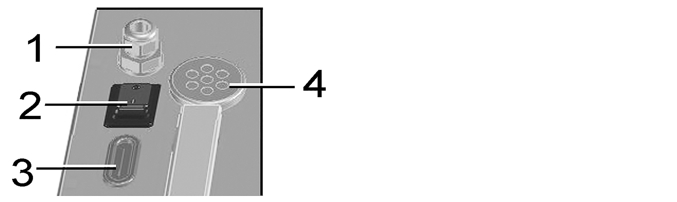
1
Cable feedthrough
2
Cable feedthrough
3
Main switch
4
Membrane grommet with slot
- Guide connection cables of the control units and additional components through cable feedthroughs [1] or [2] into ventilation unit. Ensure seal integrity (IP protection).
- Make electrical connections according to wiring diagram. For connection variants of the additional components → installation instructions of the accessories.
- Insert the electronics slide-in module into the electronics compartment.
- Insert internal cover into the bottom housing rail, close it and secure it with 4 screws (bayonet lock).
- Fit front panel in the two lugs and close (2 magnets).
- Switch the mains fuse on.
- Set the main switch to position I/On. The LEDs on the RLS 1 WR switch on.
- Install control unit(s) → Wiring diagrams.
- Carry out a function test and put the ventilation unit into operation → Commissioning.