Installation of RLS 45 O and RLS 45 K
- Take off frame of room air control.
- Set up unit pairs.
Unit pair** | Ventilation unit Fan1* exhaust air | Ventilation unit Fan2 |
1 | Unit 1.1 | Unit 1.2 |
2 | Unit 2.1 | Unit 2.2 |
3 | Unit 3.1 | Unit 3.2 |
* In the cross-ventilation operating mode, this ventilation unit switches to exhaust air.
** In case of an uneven number of ventilation units, the smaller number of units is connected to the fan 1 terminals.
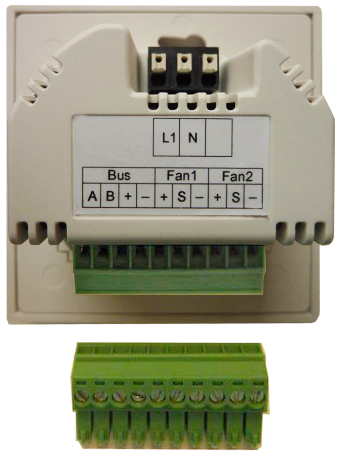
- Connect ventilation unit cables of the same Fan1 or Fan2 group to the plug-in connection terminal → Connection and wiring diagrams in the appendix. If necessary, use a separate distribution box.
 Recommendation: If there are more than 2 ventilation units, install the room air control in a switch box (to be supplied by the customer). This provides sufficient space for the connection of the cables to the room air control
Additional ventilation units can be used when using PP 45 LT power units.
- Insert room air control in the flush-mounted box and screw down to flush-mounted box with 2 screws.
- Fit frame. Ensure that the sensor opening lies above the integrated PP 45 HYI (if present).
- Commissioning ventilation system→ .