Electrical connection
Observe the applicable regulations for electrical installations, e.g. DIN EN 50110-1 and DIN EN 60204-1, in Germany in particular VDE 0100 with the corresponding parts.
 DANGER due to electric shock
Observe the safety rules of electrical engineering. Before taking off covers and before installing the electrics, shut down all supply circuits, switch off mains fuse, check that no voltage is present, secure against being accidentally switched back on and position a visible warning sign.
DANGER Risk of short circuit/fire if moisture penetrates the electronics compartment. Short circuits and fire can lead to serious injuries with fatal consequences.
Ensure correct, tight cable feed through the cable glands and long-hole diaphragm grommet.
CAUTION Risk of injury due to sharp edges on sheet metal/break-outs in the housing or in the electronics compartment.
Wear protective gloves. Carefully guide connecting cables into unit. Do not damage cables.
 If the connecting cables are too short, the electronics unit cannot be fully pulled out and fitted on the housing. Ensure connection cables of a sufficient length inside the ventilation unit.
A fixed wiring for the mains connection is mandatory. The power cable is already wired inside the unit and led out of the unit.
Take electronics unit (with A1 main board) out of ventilation unit and attach as described below.
- Switch the mains fuse off.
- Remove the front cover → WS 160 Flat: Front cover installation aid set or WS 300 Flat: Front cover installation aid set.
Figures: WS 160 Flat ventilation unit
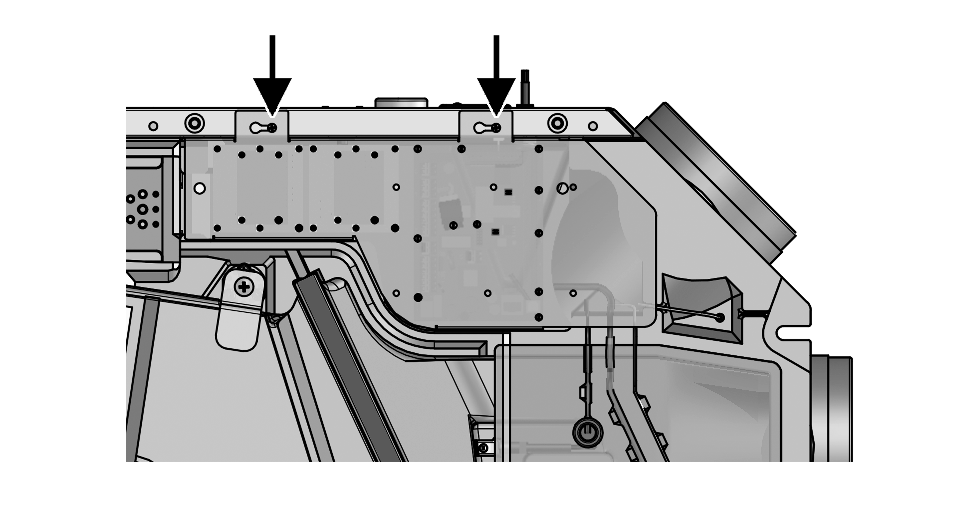
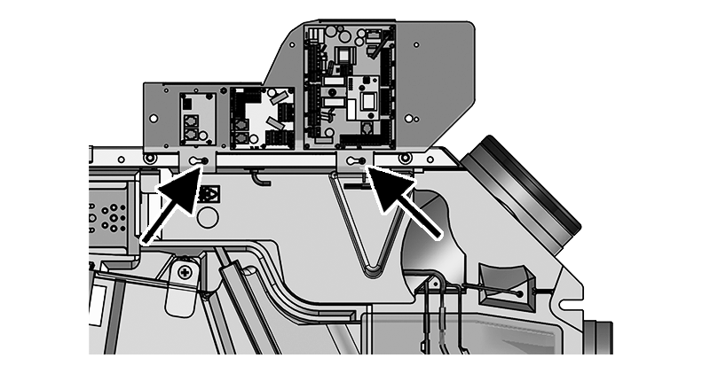
Arrow | Fitting studs |
Figures: WS 300 Flat ventilation unit
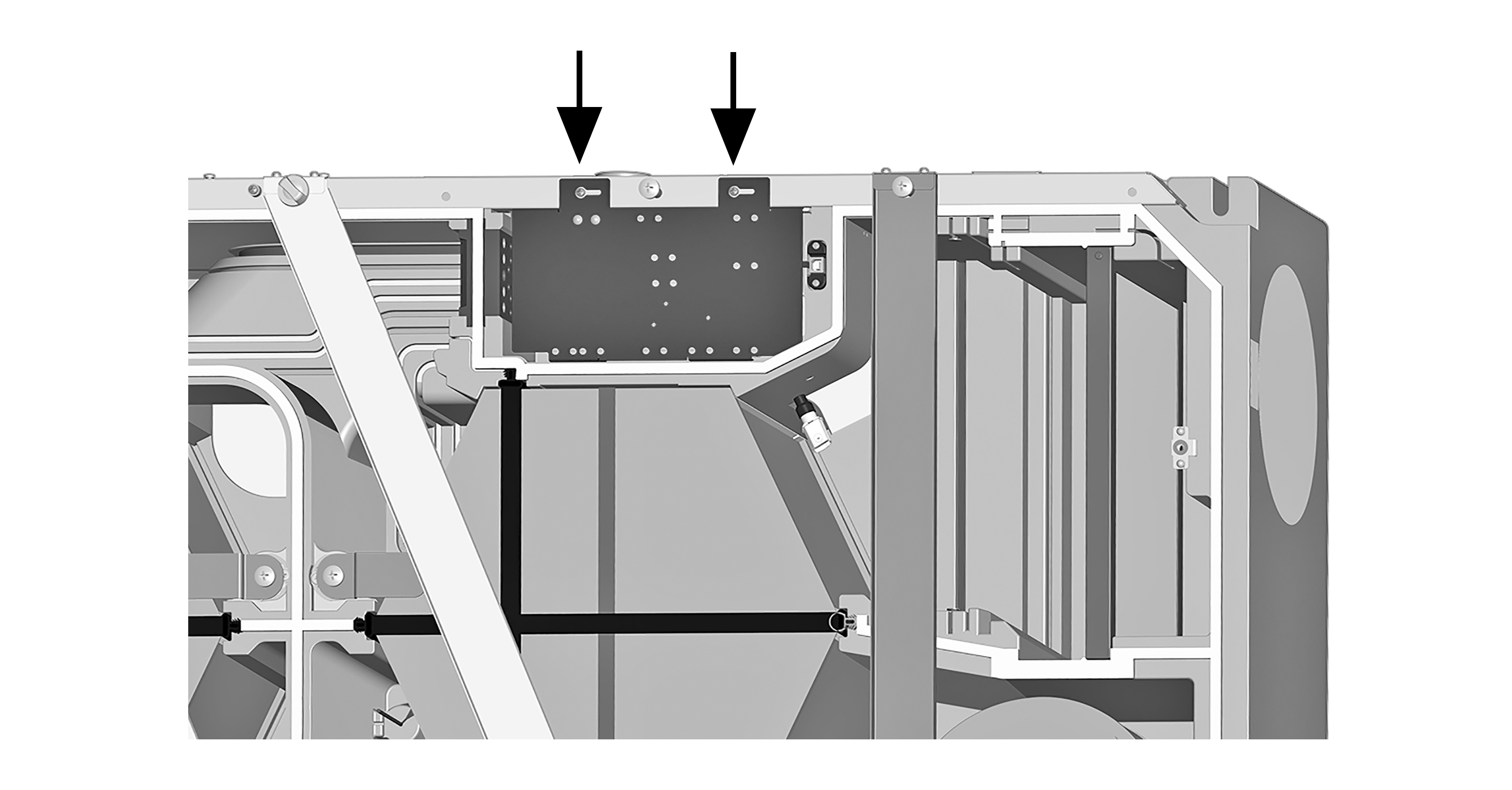
Arrow | Fitting studs |
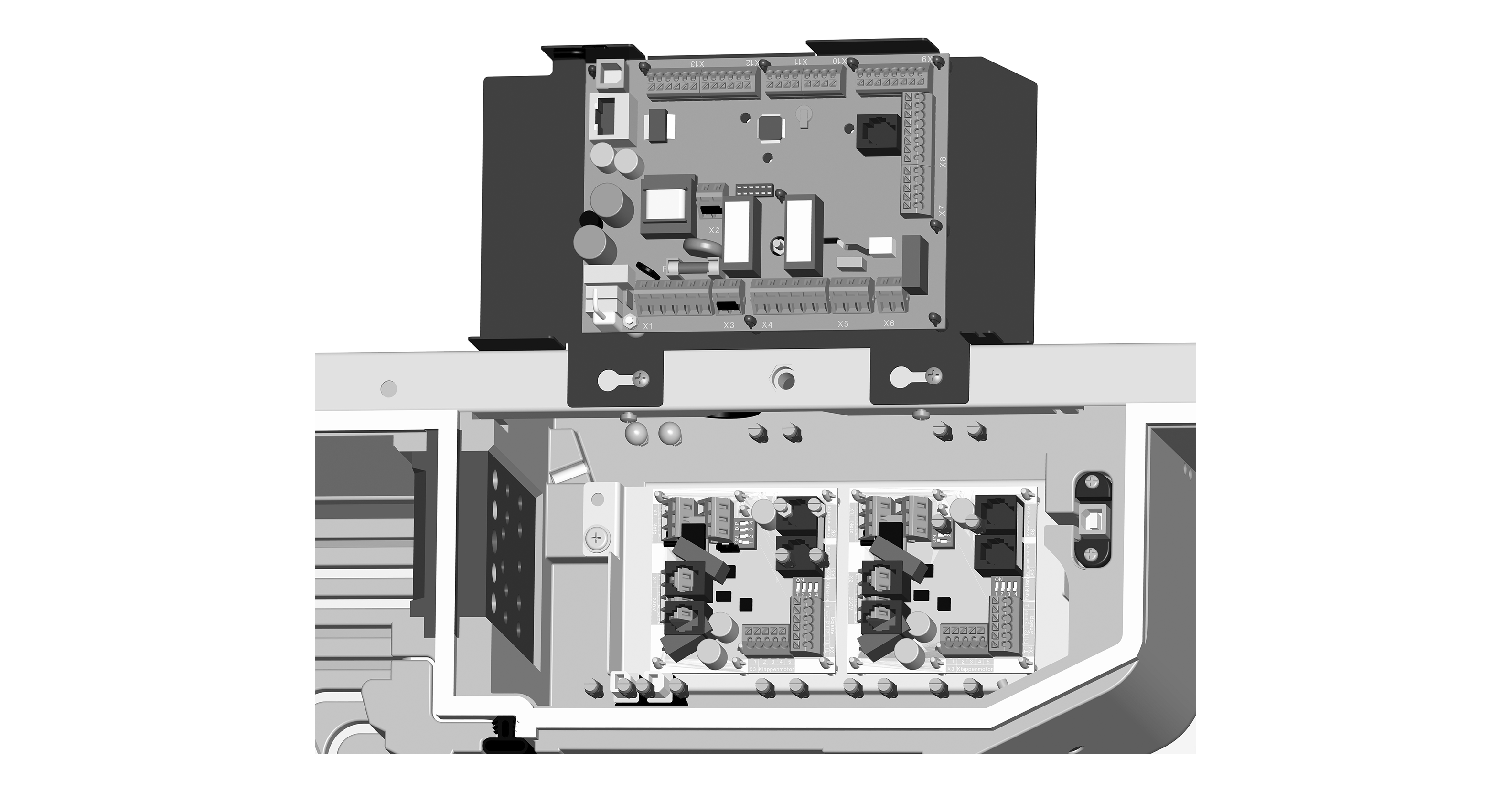
- Slightly loosen the two screws on the electronics unit.
- Take the electronics unit out of the ventilation unit and attach to studs.
- Install optional additional circuit board(s) ZP 1 and/or ZP 2 in the slots and connect with the provided connection cables. Check DIP switch settings and adjust if necessary. For electrical connection and DIP switch settings → installation instructions for respective accessories.
- Plug optional KNX plug-in module (K-SM) or EnOcean plug-in module (E-SM) into slot X01 of the main board →installation instructions of the accessories.
- Guide connection cable of control units and additional components through cable feedthrough(s) into ventilation unit. Ensure seal integrity (IP protection).
- Produce electrical connection: Wire up electrics of connection cables according to wiring diagram → Circuit diagrams, wiring diagrams.
- For connection variants of the additional components → installation instructions of the accessories.
- Install control unit(s) → and installation instructions of the accessories.
- Insert and screw down electronics unit.
- Attach front cover(s) → WS 160 Flat: Front cover installation aid set or WS 300 Flat: Front cover installation aid set.
- Run function test: Switch the mains fuse on. The LEDs on the RLS 1 WR switch on.
- Download commissioning software. For system requirements and download → Commissioning.
- Set up and regulate ventilation unit.